|
|
|
Ring System Testing
Synchronisation is concerned with the timing of traffic between network elements within an SDH network.
The TN-4XE can synchronise to any external signal that is traceable to a primary reference clock or to its own internal oscillator.
Synchronisation source selection can be carried out automatically under software control or an operator can choose a source.
At initial start up (or after a cold restart) the multiplexer is set to automatically use its internal oscillator as the synchronisation source.
The synchronous equipment timing source (SETS) function exists on each aggregate card.
This means in the event of the master aggregate card failing the SETS control is automatically passed to the backup aggregate.
The TN-4XE provides two 2MHz external synchronisation outputs, which are locked to the selected input timing source.
The source of the synchronisation signal may be selected from:
· Either of the two external synchronisation input ports.
· An STM-4 port on an aggregate card.
· An STM-1e or STM- 1o port on a tributary card.
The tn-4XE has two control circuits for choosing a synchronisation source (see diagram below).
These are:
The selection mechanism of the SETG and the ESO are identical, however each can select a different synchronisation source and the ESO can take it’s timing from the SETG.
The SETG and ESO synchronisation source hierarchy lists, contain up to four synchronisation sources listed in order of selection preference.
The internal reference oscillator is also available to the SETG if none of the list entries are usable. These lists are configured by the operator from the CAT. The SETG can be an entry in the ESO hierarchy list.
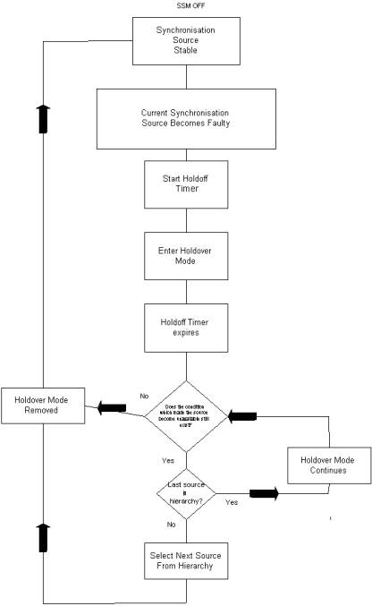
This block diagram,shows the decision process used for selection of a source,using its position in the hierarchy list as the selection criteria.
The operator can override the automatic selection process and force the network element to use a specific source; this source is then used irrespective of its condition. The forced command overrides the current source selection.
The forced switch command can use any source that is available to the multiplexer; this includes sources that are not in the hierarchy table. Where the force command is used and the destination source is faulty, the SETG will go into holdover mode.
If there are no sources in the hierarchy list available, or the operator applies a forced switch to faulty source, then the multiplexer enters holdover mode. This mode maintains synchronisation timing for the multiplexer for 48 hours.
There are two ways to exit holdover mode:
· If a synchronisation source from the list becomes available.
· If the forced switch is removed.
The ESO synchronisation selection is similar to the SETG. Again the operation is automatic, controlled by the source hierarchy table. The source selection is similar to the SETG with the following exceptions:
· The ESO signal is squelched if no synchronisation source is selected from the hierarchy.
The section below shows the commands that were used to set the synchronisation for our TN-4XE’s.
Configuring SETG Synchronization.
TN-4XE/Config/Sync_source/
>>h s6-1 s8-1
Warning: (3550) Traffic may be hit,
Are you sure? [Yes,No]:y
1, OK;
This is to set taking sync off Port 1 of the STM-4 agg card in slot 6, with a standby source of the STM-4 agg card in slot 8, with a final hold over option if both these sources fail.
TN-4XE/Config/Sync_source/
>> h none
Warning: (3550) Traffic may be hit,
Are you sure? [Yes,No]:y
1, OK;
This is is to set the 4XE in holdover mode i.e. using its own internal clock to sync off.
The diagram below shows the synchronisation setup that we have used when commissioning our 4 TN-4XE’s.
From the diagram it can be seen that KIB-1 is set to synchronise from its own internal time source, and KIB’s-2 / 4 take there timing from KIB-1.

