|
|
|
ADM System Testing
During this part of the commissioning process an understanding of what Add Drop Multiplexers (ADM) actually achive was required. It was therefore decided to include a basic overview of ADMs in this section of the site. It was also felt appropriate to include information on various other types of equipment such as cross connect switches and to show how they would intergrate together to form an SDH network.
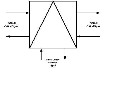
The main function of the Add Drop Multiplexer is to add (insert)
and drop lower order electrical signals usually HDB3 into the higher order STM-1 signal.
The ADM can also cross connect lower order paths internally.
The symbol used to represent an ADM is shown in the diagram below:
The real benefit of SDH over PDH is the ability to drop or insert channels to customers.
The Add drop multiplexer is an integral part of this ability.
The ADM is produced at various rates or operation as detailed in the table below:
| STM Standard | Bit Rate |
|---|---|
| STM-1 | 155.520Mbits/s |
| STM-4 | 622.080Mbits/s |
| STM-16 | 2448.320Mbits/s |
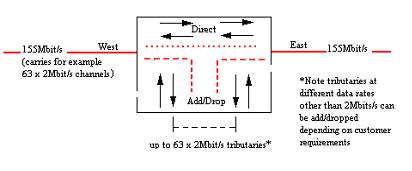
An initial example of ADM operation is given by the diagram below:
As mentioned the main problem with the demultiplexing of a PDH signal
is that the whole circuit must be demultiplexed to provide for example
a 2Mbps link.
This is more easily appreciated if a typical example is considered.
Assume three switching centers / exchanges located in different towns/cities
are interconnected by 140Mbps (PDH) trunk circuits.
A business customer, with sites located somewhere between them,
makes a request to link the sites with a 2Mbps leased circuit to
create a private network.
Because it is not possible to identify a lower bit rate channel
from the higher order bit stream, the operator must fully demultiplex
the 140Mbps stream down to the 2Mbps
level before this can be allocated to the customer. This stream must
then be remultiplexed back into the 140Mbps stream for onward transmission.
Although the customer request was fairly simple the actual process that must be followed is extensive and the equipment is very expensive.
This type of demultiplexing operation would be performed by an ADM without the need for extensive demultiplexing.
SDH ADM’s can be configured and reconfigured remotely to provide any desired bandwidth mix without the need for demultiplexing. The general principle is shown in the diagram below. Redundant links are used between each pair of SDH multiplexers and these can be brought into service using commands received from a remote network management station.
One main advantage of the ADM is its ability to be employed within a Ring type network Topography. The following diagram shows an example of this:
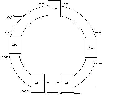
In the example shown above the ADM’s are 16 by 2 Mbit/s types.
This gives this ring the ability to add a 2Mbit/s signal at any of the ADM’s and drop that signal at any ADM within the network which, again is a great advantage over PDH systems.
One other function of the ADM is to provide cross connection facilities for low order paths. In the above diagram a 2Mbit/s circuit can be added at SMX 2 and sent out East to SMX 3.
SMX 3 can cross connect it (West to East) and send it (East to West) to SMX4. All of this is achieved by software control.
Another major advantage of Add/Drop Mux equipment showing the flexibility of routing controlled by software. No longer is manual jumpering required to reroute a circuit as needed by a Mux Mountain.
This means large savings in manpower, travelling time and equipment expenses as routing can be controlled from a central point controlled by software.
These form the first level of a SDH network. In addition to STM-1 ADMs there are also STM-4 and STM-16 ADMs.
These are used at the 2nd level of a SDH network where a line rate 4 (622Mbit/s) is utilised. An STM-4 ADM has the capacity to add/drop at the same rates as an STM-1 ADM but can also add/drop & cross-connect VC-4.
SDH line systems are used to multiplex and transport STM-1 or 140Mbit/s PDH signals between terminal repeater stations. It should be noted that the optical signal may need regenerating by using Intermediate Regeneration (IR) equipment to transmit over long distances. Common line systems used in SDH networks are STM-4 and STM-16.
The STM-4 line system multiplexes 4 tributary signals together to form a 622.08Mbit/s aggregate signal. The tributary ports can be configured to accept either STM-1 SDH or 140Mbit/s PDH signals. The POH of the STM-1 inputs are removed and the AU-4s created are then byte interleaved. A new section overhead is then added and the new signal is converted to optical format for transmission down an optical fibre.
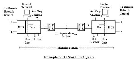
PDH signals are converted to AU-4s for transmission over the system.
For distances in excess of 30km an Intermediate Regenerator (IR) may be required. This consists of an optical receive line card followed by an optical transmission line card. In-between the receive and transmit cards the signal is converted back to electrical format so that it can be regenerated.
Timing for the line system can be clocked from an external timing source by the use of a built in timing input port. The timing signal can be extracted at the output port for further use in another section of the network.
There are two major differences between an STM-16 line system and a STM-4 one. The first difference is that it can accept 16 tributary signals, either STM-1 or 140Mbit/s PDH.
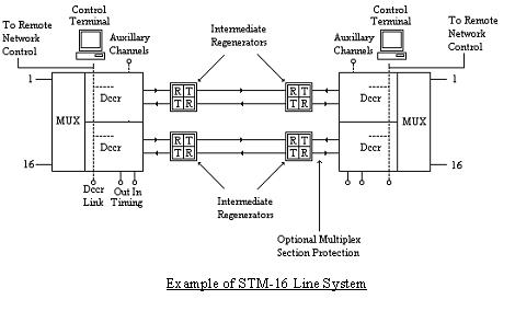
The second and major difference between them is that the STM-16 line system can incorporate an optional multiplex section path to provide a back up path in case the primary fibre optic path fails. Network operators do not always use the optional multiplex section path as this is dependent upon the cost required to provide the path balanced against the traffic importance allocated to the link.
The basic function of SDH cross connect equipment is to switch network signals, usually in the form of STM-N, in the same way that a telephone exchange switches calls.
Cross-connects are known as DXCs within Europe and DCSs in the United States. For the purposes of this assignment we shall use the DXC classification. Normally the type of DXC is indicated in the format DXC p/q, where p is the hierarchical order of the port bit rate and q is the hierarchical order of the traffic component that is switched within that port bit rate.
DXCs divert signals between traffic streams and can be fully controlled by software. Also a DXC integrates the functions of line termination/multiplexing and the automatic reconfiguration of signals into one unit. This ensures that traffic routes can be easily changed to allow for congestion, link failures and to minimise costs.
Some cross-connect designs allow all traffic interfaces to be in PDH form for compatibility with existing equipment. In particular, these designs might allow the p hierarchical level in a DXC p/q cross-connect to be at either 34 or 140 Mbit/s in PDH format, as an alternative to STM-1. This is so that network flexibility becomes available where a SDH infrastructure does not yet exist. In these cross-connects, a port at 34 or 140 Mbit/s can include embedded PDH multiplex equipment for internal conversion to and from 2 Mbit/s thus providing a multiplexer function between PDH and SDH areas of the network.
DXCs occur in two main types, high order and low order.
Higher order cross-connects can be used to switch up to 64 x STM-1signals. They are designated as DXC 4/4.
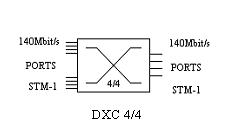
A DXC 4/4 can switch the following signals:
The switch deals with the various inputs to be switched by processing them all into AU-4s before actually switching them.
Lower order cross-connects (DXC 4/1 or 1/1, the "1" denoting primary rate at 1.5 or 2 Mbit/s) are used for time switching leased lines, consolidation, and service restoration. They switch traffic components down to primary rate, usually having options to switch alternatively at the intermediate rate of 34 or 45 Mbit/s.
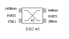
The DXC 4/1 is both a switch and a multiplexer. It can switch low order paths into 140Mbit/s, or STM-1, signals. Also it has the ability to cross connect any VC type (VC-12, VC-2, VC-3 & VC-4). It can be configured for use with a wide range of Plesiochronous & Synchronous interfaces.
In actuality DXCs are usually combined to provide maximum switching flexibility.
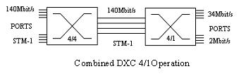
This of combination of switches is extremely versatile e.g. a VC-12 can be switched into an STM-1 signal purely by software control.
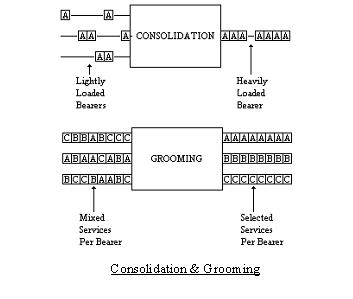
One of the major uses of DXCs is that of consolidation and grooming. Consolidation is a process of taking several partly used incoming stream, from various users, and combining them into one outgoing stream. Grooming is the process of combining several streams owned by a customer into one steam i.e. several different locations can present their traffic to the SDH network where it can be combined into one stream for delivery to a final destination location. Also grooming can be used to combine the same types of traffic on one stream e.g. voice, data etc. The Diagram below gives schematic examples of this.
We have now examined all the major components of an SDH network and it is time to show how the various network topologies, levels and hardware fit together.
Traditional networks make use of mesh and hub (i.e., star) arrangements, but with the help of DXCs and hub multiplexers SDH allows for far greater flexibility. SDH also enables the combining of standard network topologies with rings and chains of ADMs to improve flexibility and reliability across the core and access areas of a network.
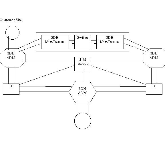
We have already seen how ADMs can be used to provide a ring network but in reality a SDH network is liable to be much more complicated. The diagram below gives an example of how SDH ADMs and DXCs can be combined together to provide a realistic network.
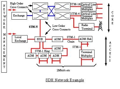
Another example is also provided below to give a schematic representation of how a SDH network may be tiered.
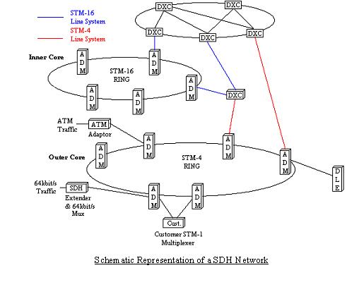
In the diagram a client is accessing the SDH network at the STM-4 ring via a dual parented SDH-1 multiplexor. Also a DLE is accessing the network along with other network elements such as 64kbit/s and ATM traffic links. This shows the ability of a SDH system to convey mixed traffic types over the same network.
In the Inner core layer at the lower levels ADMs are generally used. As we move up into the higher levels these are replaced by DXC equipment. In practice the higher level of the inner core could be connected to a large gateway link (i.e. International Gateways) to allow large volumes of STM-N traffic to be routed to other large SDH networks.
Most SDH networks are based on the principles illustrated above i.e. STM-1 & 4 rings in the outer core and a mixture of STM-16 and DXC’s in the inner core.


