|
|
|
Point to Point System Testing
This section will discuss why Path Protecting is required and also how it is achieved within a Point-to-Point system.
SNC-P path protection implies that each VC-4 (STM-1) is broadcast over two separate routes.
In the event of a cable cut or equipment failure,
the end-node selects the best signal from the working and protected signals arriving via different routes.
Hence, the switching time is very fast (below 50ms),
as no particular protocol is needed between nodes to allow for restoration.
SDH equipment can be connected to Uninterrupted Power Supplies (UPS) and/or be provided by power from standby generators, to protect against mains failures.
To ensure that if an item or card within an SDH network fails, that may cause a serious network outage, duplicate standby equipment may be installed. This equipment is automatically switched in if a failure occurs i.e. there may be a dedicated standby tributary card that traffic will automatically route through if a failure occurs. Another advantage of standby equipment is that it can be brought on line to allow essential maintenance to take place.
This is used when end-to-end path of service failure occurs. This is achieved by allocating spare network capacity which traffic can be rerouted into if a loss of signal occurs. Rerouting algorithms within network element software controls this process. Restoration may also be achieved by being assigned capacity that was being used by lower priority traffic.
Restoration offers good flexibility but can be extremely slow (seconds or minutes to hours) that has a major effect on real time data. This slowness is due to the complex rerouting algorithms that are required as well as restoration being initiated only when the failure is detected.
Duplicating traffic in the form of Virtual Containers, and transmitting it simultaneously in two separate directions, is known as “dedicated path” or “VC trail” protection. The receiving network node compares the two received signals and then selects the better quality signal. If a failure occurs on one of the paths the receiving node automatically selects the other VC path.
An example of this type of protection is a path protected ring in which traffic is transmitted in both directions around the ring from the originating station.
Unlike dedicated path protection that involves switching at the end of an “end of path”, subnetwork connection protection (SNCP) involves switching by intermediate nodes to restore service. See the diagram below for an example of SNCP.
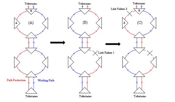
(A) illustrates the normal working/path protection links of or network example.(B) illustrates that dedicated path protection switches in if a failure occurs on the working path. However, if another failure occurs on the remaining working link there is now no remaining dedicated path protection to switch too. (C) illustrates how this is overcome by the use of SNCP by enabling subnetworks to switch to a protection path rather than the entire link.
SNCP can be seen to offer greater network resilience than simple dedicated path protection.
This type of protection operates on traffic links between two connected multiplexing nodes. Two physical fibres are used to connect the nodes and if one fibre fails, traffic will be automatically switched on to the other fibre to ensure connection is maintained. These fibres can be routed over divers paths so that if a cable is physically cut then the other cable will be unaffected.
Self-healing rings provide diverse route protection and comprise two types; those that protect section layers and those that provide path layer protection. These can further be further subdivided into bi-directional or unidirectional rings.
The Dedicated Path Protection diagram below illustrates a dedicated protection ring. Traffic is duplicated and sent on both routes on the ring.
It can be seen that although this offers protection it is a waste of network capacity.Multiplex section shared protection rings (MS-SPRing) as illustrated below overcome this wasted capacity.
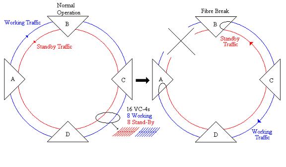
MS-SPRings do not use a dedicated path for the protection of every link. They provide protection by reserving capacity for the protection of several working paths. In the event of a failure all traffic on a section is switched. It appears at first that MS-SPRing does not offer any further advantage over dedicated path rings. However the MSPRING Example diagram below illustrates the advantage to network capacity much clearer.
The Example illustrates that between (A) and (B) eight STM-1 channels
are required to route traffic across route (w1) and eight STM-1 channels
are required to route this traffic in the other direction, route (p1).
This restricts the network to 8 working STM-1 channels on each section of
the ring so if traffic is routed between (D) & (E) then all the capacity
will be used will a total of 16 user channels only.
If however, MS-SPRing is used, traffic between A&B still uses eight STM-1
channels but the other nodes on the ring can share the eight channels
used for protection. As can be seen by the MSPRING Example diagram,
this means that it is possible to have six 8 channel links between the
nodes (A-B, B-C, C-D, D-E, E-F & A-F), allowing a maximum of 48 user
channels on this network.
It should be noted that the various protection schemes discussed can be
mixed and matched during network design to give an overall protection
scheme that suits the requirements of the network operator.
SPRings are often used in ring topology networks but restoration
is often chosen in highly complex meshed architectures.
The APS(Automatic Protection Switching) specified in ITU-T G.783,
is applied for line switching procedure using SDH K1/K 2 byte and its
restoration time is within 50 msec. In the 1+1 configuration,
the same signal is transmitted over the working and standby lines.
In the 1:1 configuration, the idle signal or extra traffic signal
are transmitted on the standby line.
Both 1+1 and 1:1 protections performs 100% restoration, while the 1:N protection perform partial restoration.
MS-SPRing: performs ring switching or span switching between nodes. Each working traffic and protection traffic is transmitted bidirectionally over spans. The protection traffic can be flexibly used for extra traffic, not protection.
2F MS-SPRing:Each fibre handles both working traffic and protection traffic, and half of the bandwidth can be used for working and remaining for protection which protects the working traffic transmitting in the opposite direction around the ring. Traffic is terminated at each node around the ring, so 2F MS-SPRing can reuse the bandwidth and provide effective networking solution.
4F MS-SPRing: Each fibre handles working traffic or protection traffic which are transmitted over one fibre pair respectively. There are two protection switching modes, Ring protection switching and Span protection switching. Moreover 4F MS-SPRing has twice capacity of 2F MS-SPRing, so 4F MS-SPRing can be suited for requiring bountiful capacity and/or highly reliable protection such as backbone network.


